
Imagine designing a water pipeline that should deliver water smoothly across an entire facility.
The pipe size is correct, the pump is powerful enough, and every component has been manufactured accurately. Yet the system still loses pressure, consumes excessive energy, and fails to perform as expected.
In many engineering systems, the problem is not the equipment itself. The real challenge is understanding how fluids behave while moving through the system.
Whether it is water flowing through pipelines, air moving through HVAC systems, fuel travelling through an engine, or airflow around an aircraft wing, fluid behavior directly affects performance, efficiency, and reliability.
This is why understanding Fluid Flow Basics for Mechanical Engineers is essential. Engineers who understand fluid mechanics can design safer, more efficient, and more reliable systems across a wide range of industries.
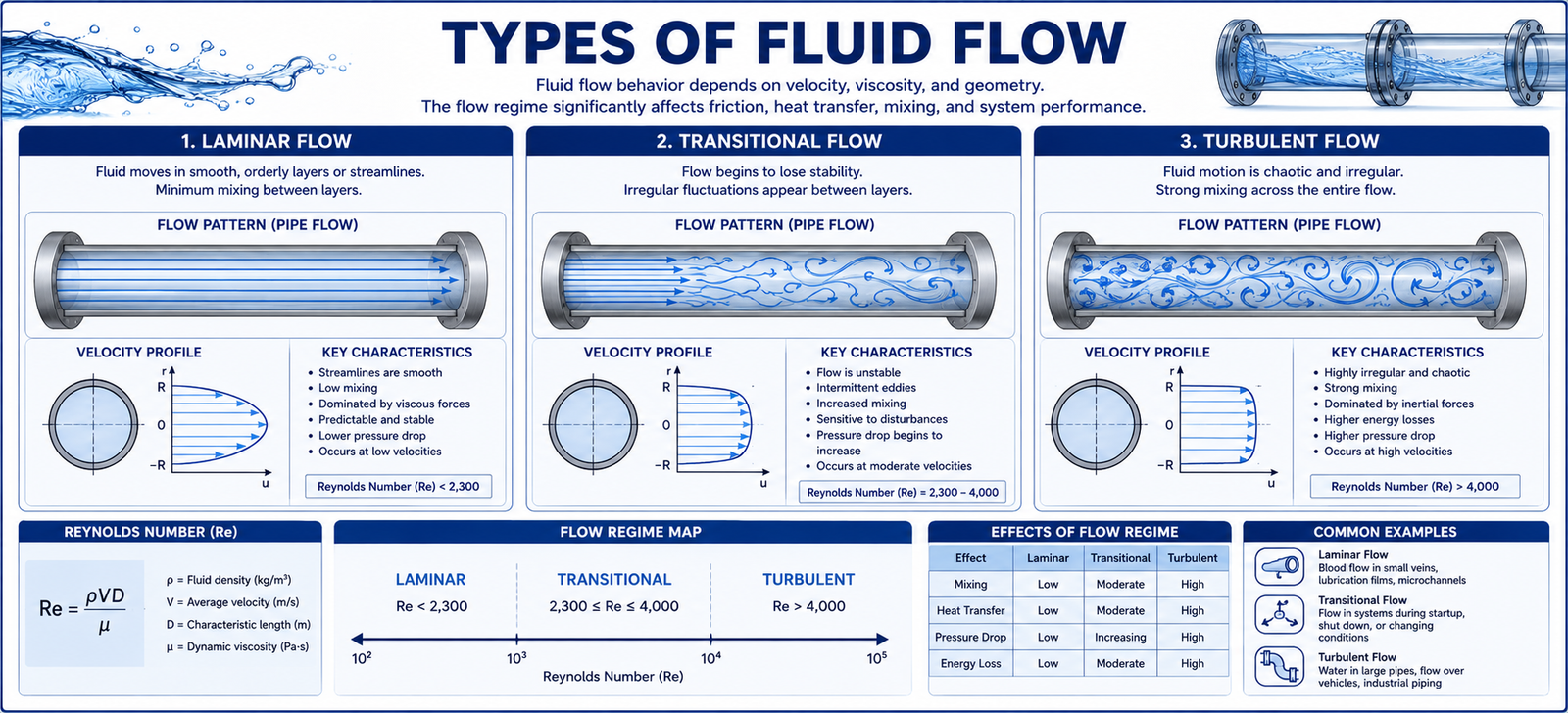
Not all fluids move in the same way. Engineers classify fluid flow into different categories based on how fluid particles behave during motion.
Laminar flow occurs when fluid moves in smooth and orderly layers. There is very little mixing between adjacent layers, making the flow predictable and stable.
This type of flow is commonly observed in low-speed systems and applications where precise fluid control is required.
Turbulent flow is chaotic and involves significant mixing of fluid particles. Swirls, eddies, and fluctuations occur throughout the flow field.
Most industrial pipelines, HVAC systems, and high-speed engineering applications operate under turbulent conditions.
Transitional flow represents the intermediate stage between laminar and turbulent flow. Small disturbances can cause the flow to shift from stable to chaotic behavior.
Understanding these flow regimes helps engineers predict system performance and select appropriate design parameters.

Several fundamental principles help engineers understand and predict fluid behavior.
The continuity equation states that mass remains conserved within a closed flow system.
As fluid passes through a smaller area, its velocity must increase to maintain a constant flow rate. This principle is widely used in pipe design and hydraulic systems.
Bernoulli’s Principle explains the relationship between pressure, velocity, and elevation in a flowing fluid.
As velocity increases, pressure decreases. This concept plays an important role in aircraft aerodynamics, pumps, turbines, and hydraulic systems.
This concept is also related to Aerospace Engineering Design Principles.
Reynolds Number helps engineers determine whether a flow will be laminar or turbulent.
It depends on fluid velocity, density, viscosity, and characteristic dimensions of the system.
This value is widely used when designing pipelines, ducts, pumps, and flow control equipment.
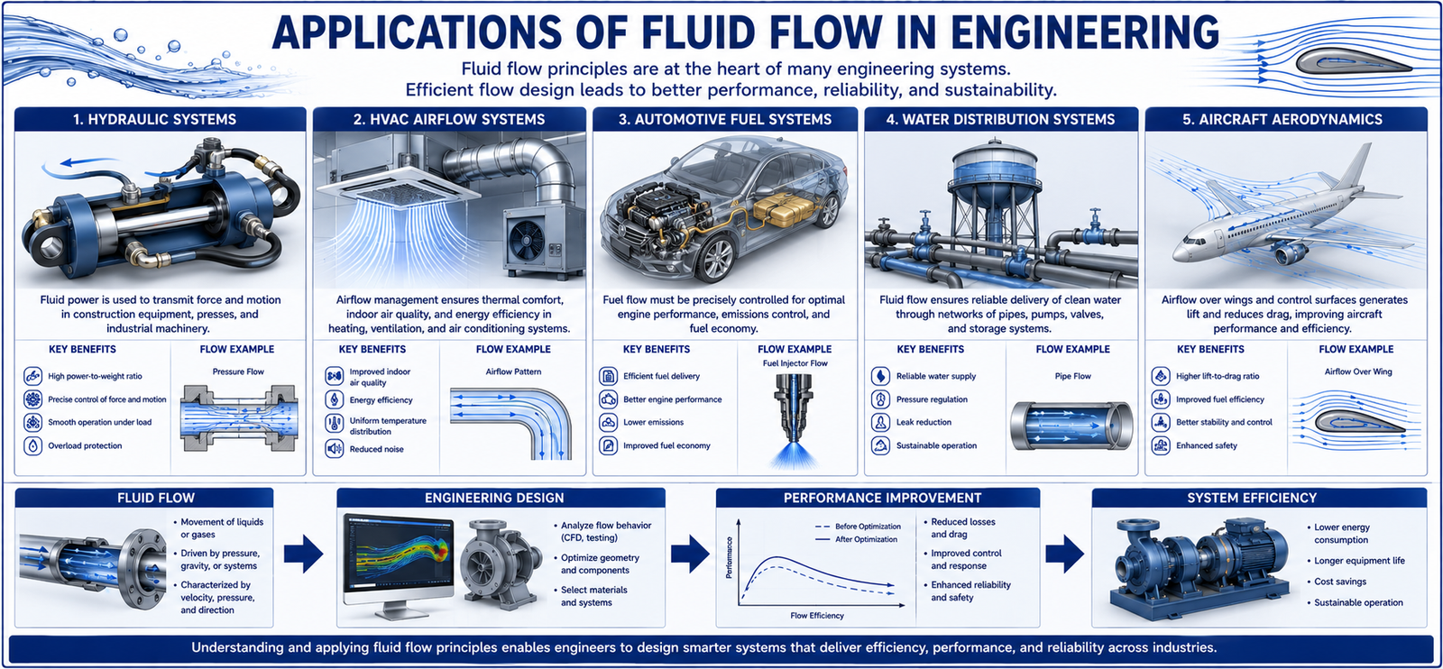
Fluid flow principles are used in almost every engineering industry because fluids play a major role in energy transfer, cooling, lubrication, and transportation.
In automotive engineering, fluid flow controls fuel delivery, lubrication systems, cooling circuits, and aerodynamics.
HVAC systems rely on airflow analysis to maintain comfortable temperatures and efficient energy usage.
Hydraulic machinery uses pressurized fluids to generate powerful mechanical motion.
Water treatment and distribution systems depend on fluid flow calculations to ensure reliable supply and pressure management.
Aircraft designers study airflow around wings and fuselage structures to improve lift, reduce drag, and increase fuel efficiency.
These applications are part of Real-World Engineering Systems.

Today, engineers use Computational Fluid Dynamics (CFD) software to study fluid behavior before physical prototypes are built.
CFD simulations allow engineers to predict pressure distribution, velocity patterns, turbulence levels, heat transfer, and flow efficiency.
Instead of relying solely on physical testing, engineers can evaluate multiple design options digitally and optimize performance before manufacturing.
This process helps reduce development costs, shorten testing cycles, and improve product reliability.
CFD is an important part of CAE in Engineering Design, where digital tools help engineers make better design decisions.
Fluid flow is one of the most important concepts in mechanical engineering because it influences the performance of countless engineering systems.
From pipelines and hydraulic systems to aircraft and HVAC equipment, understanding fluid behavior helps engineers improve efficiency, reduce energy consumption, and enhance reliability.
By understanding fluid flow principles, flow types, and simulation techniques, engineers can design safer and more effective systems for real-world applications.
At 4Dimensions Infotech Pune, students gain practical knowledge of engineering fundamentals, CAD, CAE, simulation tools, and real-world design workflows.
Understanding concepts such as fluid mechanics, heat transfer, mechanical design, and engineering analysis helps build a strong foundation for future engineering careers.
👉 Contact 4Dimensions Infotech and start building industry-ready engineering skills today.
1. What is fluid flow in engineering?
Fluid flow refers to the movement of liquids or gases through a system.
2. What are the main types of fluid flow?
Laminar flow, turbulent flow, and transitional flow.
3. What is Bernoulli’s Principle?
It explains the relationship between pressure, velocity, and elevation in a flowing fluid.
4. What is Reynolds Number used for?
It helps determine whether fluid flow is laminar or turbulent.
5. Why is CFD important?
CFD allows engineers to analyze fluid behavior digitally before manufacturing, reducing cost and improving performance.
© 2025 4Dimensions Infotech. All rights reserved. | Best Design Engineering Training Institute in Pune
Start your journey with the best design engineering training institute in Pune.