At 4Dimensions Infotech Pune, students enrolled in a CAD Design Course, SolidWorks Course, or CATIA Course quickly discover that sheet metal components are everywhere. From automotive body panels and electrical enclosures to industrial machinery and consumer products, sheet metal is one of the most widely used manufacturing materials in modern engineering.
Because of its strength, lightweight nature, and cost-effectiveness, engineers rely heavily on Sheet Metal Design Principles when developing products for mass production. However, designing sheet metal parts requires more than simply creating a 3D model.
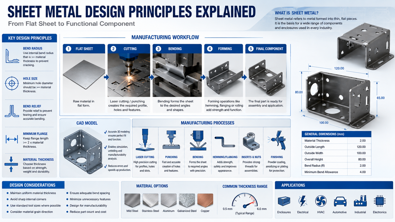
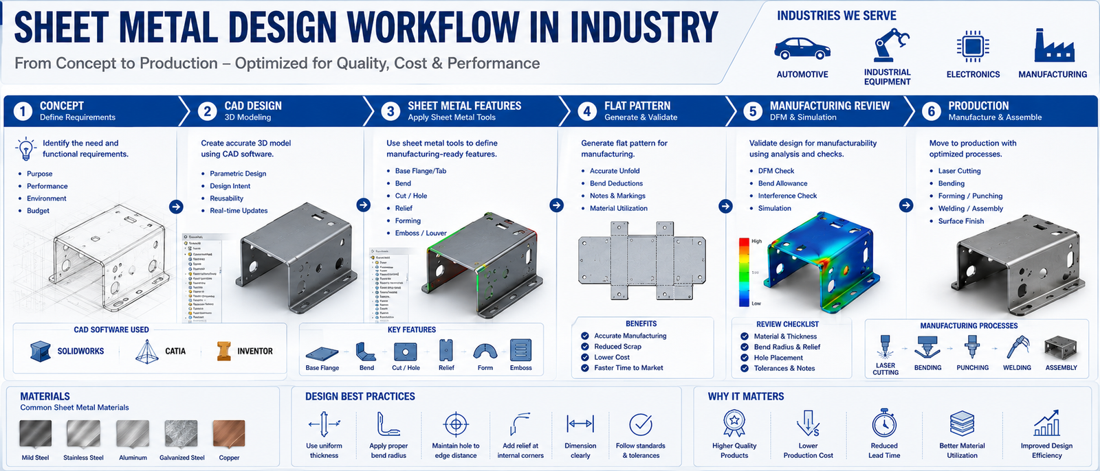
Engineers must understand how metal behaves during cutting, bending, punching, and forming operations. Even small design mistakes can increase manufacturing costs, create production issues, or cause component failure.
Modern industries use specialized CAD software such as SolidWorks and CATIA to create manufacturable sheet metal designs. These tools allow engineers to simulate bends, generate flat patterns, and optimize components before production begins.
Understanding Sheet Metal Design Principles is therefore an essential skill for mechanical engineers, product designers, manufacturing engineers, and students pursuing careers in modern product development.
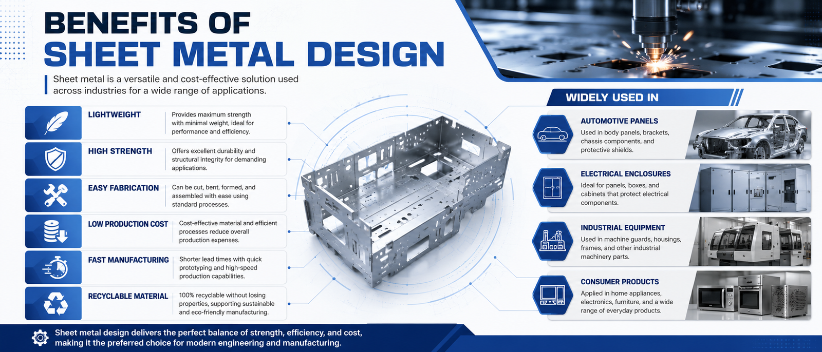
One of the biggest reasons engineers use sheet metal is its ability to provide high strength while maintaining low weight. This combination makes it ideal for industries where performance, cost, and manufacturability must be balanced.
Automotive manufacturers use sheet metal to reduce vehicle weight and improve fuel efficiency. Electronics companies use sheet metal for protective enclosures, while industrial manufacturers use it for machine covers, brackets, cabinets, and structural assemblies.
Modern manufacturing environments require designs that are easy to produce at scale. By following proper Sheet Metal Design Principles, engineers can reduce waste, improve production speed, and lower manufacturing costs.
This concept directly relates to Design for Manufacturing (DFM), where engineers design products specifically for efficient production.
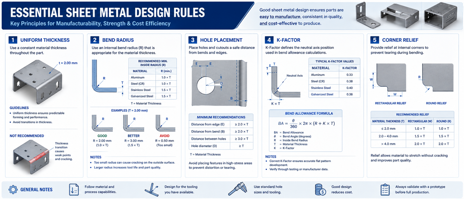
One of the most fundamental Sheet Metal Design Principles is maintaining consistent thickness throughout the component. Sudden thickness changes create manufacturing challenges and increase production costs.
Every sheet metal material has bending limitations. If the bend radius is too small, the material may crack during manufacturing. Engineers therefore calculate bend radii carefully based on material properties and thickness.
Holes placed too close to bends or edges often deform during fabrication. Proper spacing ensures dimensional accuracy and reduces manufacturing defects.
When a sheet metal part is bent, the material stretches and compresses. Engineers use the K-factor to calculate bend allowance and ensure accurate flat pattern development.
Sharp corners create stress concentration points that may weaken the component. Using fillets and rounded corners improves durability and reduces manufacturing risks.
This principle directly supports concepts discussed in Stress Concentration in Mechanical Design.
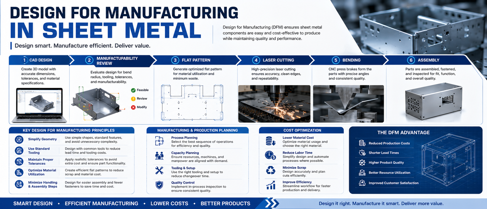
Successful sheet metal design is not only about creating a functional part. Engineers must also consider how the component will be manufactured.
Processes such as laser cutting, punching, bending, welding, and assembly all influence design decisions. Components that are difficult to manufacture increase production costs and lead times.
Modern companies therefore emphasize manufacturability from the beginning of the design process. Engineers who understand Design for Manufacturing principles can create components that are easier, faster, and cheaper to produce.
Manufacturing-focused design skills are heavily emphasized in modern Mechanical Design Courses, CAD Design Courses, and advanced engineering training programs.
Every product made from sheet metal begins with a well-planned design. Whether it’s an automotive body panel, an electrical enclosure, an industrial machine cover, or an aircraft component, following the correct sheet metal design principles helps engineers reduce manufacturing errors, lower production costs, and improve product quality.
Understanding concepts such as bend radius, K-factor, bend allowance, relief design, manufacturability, and CAD workflows allows engineers to design components that move smoothly from digital models to the production floor.
As manufacturing industries continue adopting automation, digital engineering, and Industry 4.0 technologies, sheet metal design remains one of the most valuable skills for mechanical engineers who want to build successful careers in product design and manufacturing.
Reading about sheet metal design builds your theoretical understanding, but becoming an industry-ready engineer requires practical experience with professional CAD software and real engineering projects.
At 4Dimensions Infotech Pune, students don’t just learn software—they understand how sheet metal components are designed, validated, and prepared for manufacturing using industry-standard workflows.
Whether you’re searching for an AutoCAD Course in Pune, a CAD Course in Pune, a SolidWorks Course in Pune, or an AutoCAD Course Near Me, choosing a project-based training program helps you develop the practical skills employers expect from design engineers.
Students gain hands-on experience using AutoCAD, SolidWorks, CATIA, and other industry-standard software while working on real mechanical design projects that strengthen both technical knowledge and interview confidence.
If your goal is to become a Mechanical Design Engineer, practical exposure to sheet metal design, CAD modeling, manufacturing workflows, and engineering documentation can give you a significant advantage during placements and technical interviews.
1. What is sheet metal design?
Sheet metal design is the process of designing components manufactured from thin metal sheets using operations such as bending, punching, cutting, and forming while ensuring they can be produced efficiently.
2. Which software is best for sheet metal design?
AutoCAD is widely used for drafting, while SolidWorks, CATIA, and Creo provide dedicated sheet metal design tools for creating bends, flat patterns, and production-ready models.
3. Is sheet metal design a good career for mechanical engineers?
Yes. Industries such as automotive, aerospace, industrial equipment, HVAC, and manufacturing actively hire engineers with practical sheet metal design and CAD skills.
4. Which CAD course is best for learning sheet metal design?
A project-based CAD Course in Pune or SolidWorks Course in Pune that includes real industrial projects, manufacturing concepts, and practical design workflows provides the best learning experience.
5. Where can I learn sheet metal design in Pune?
If you’re looking for an AutoCAD Course in Pune, CAD Course Near Me, or Mechanical Design Course in Pune, choose a training institute that offers practical projects, industry workflows, and placement-oriented learning instead of only software demonstrations.
© 2025 4Dimensions Infotech. All rights reserved. | Best Design Engineering Training Institute in Pune
Start your journey with the best design engineering training institute in Pune.