In mechanical design, a product is not considered successful just because it looks good in CAD. A design is only truly valid when it performs safely, reliably, and efficiently under real-world conditions. This is where Finite Element Analysis (FEA) becomes one of the most powerful tools for engineers.
FEA helps engineers test their designs before manufacturing, saving time, material, cost, and failures. In simple words…
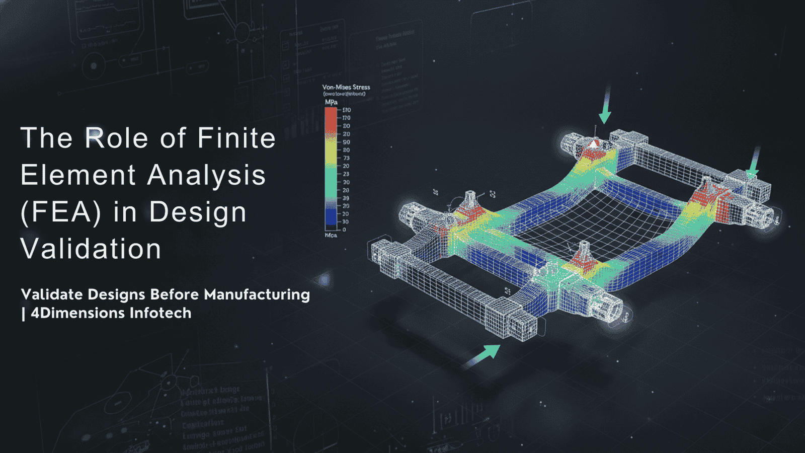
FEA allows engineers to see how a design will behave under load, stress, temperature, vibration, and real forces — without actually building it.
This article explains in a clear, easy-to-understand way how FEA works, why it is essential in design validation, and why modern engineers must learn it for industry success.
FEA is a digital simulation method that breaks a complex structure into thousands of tiny elements called nodes and elements. The software then calculates how each element reacts to applied conditions.
Instead of testing a full physical prototype, engineers run a virtual test and find:
✔ Stress concentration areas
✔ Deformation and displacement
✔ Factor of safety
✔ Failure risk zones
✔ Weight and cost optimization opportunities
Simulation = smarter design decisions.
Manufacturing a wrong design means waste of material, time, and cost.
FEA catches problems in the early stage.
Instead of building 10 prototypes, engineers may build only 1 or 2 final validated versions.
FEA helps check load capacity, fatigue cycles, thermal performance — ensuring product is safe.
Smarter design → fewer errors → reduced redesign and development effort.
In short, FEA makes design accurate, durable, and production-ready.
| Type of Analysis | Purpose |
|---|---|
| Static Structural | Stress, strain, deformation review |
| Modal Analysis | Natural frequency and vibration study |
| Thermal Analysis | Heat distribution and temperature effects |
| Fatigue Analysis | Life expectancy under cyclic loading |
| Buckling Analysis | Stability of columns, beams, frames |
| Impact/Crash Analysis | Sudden load or collision performance |
| CFD Simulation | Fluid flow and heat transfer |
Each one helps validate a different type of engineering requirement.
Clean and simplified model imported to FEA software.
Model is divided into tiny finite elements.
Finer mesh = more accurate results.
Define how the part behaves — fixed support, rotating, sliding etc.
Force, pressure, temperature, torque, gravity…
Software calculates stress, strain, deformation in all elements.
Engineers check weak areas, optimize design, repeat until safe.
Simulation → improvement → re-simulation → final approval.
| Application | FEA Helps In |
|---|---|
| Automotive chassis | Crash survival, stiffness, vibration |
| Aerospace wings & structures | Weight reduction + strength |
| Gearbox & shafts | Torque resistance, stress concentration |
| Pressure vessels | Burst pressure analysis |
| Biomedical implants | Load distribution & fatigue |
| EV battery casings | Thermal runaway simulation |
If a product can break, deform, heat up, vibrate, or fatigue — FEA validates it.
| Traditional Method | FEA |
|---|---|
| Physical prototype required | Virtual simulation possible |
| Time-consuming | Fast iteration |
| Costly | Cost-effective |
| Hard to test multiple conditions | Test unlimited variations easily |
| High risk of failure | Fail on screen, not in factory |
This is why FEA has become a global standard in design validation.
To perform high-quality simulation work, engineers must know:
✔ Strength of Materials
✔ Material behaviour under stress
✔ CAD & geometry simplification
✔ Meshing techniques
✔ Boundary condition logic
✔ Result interpretation & report preparation
Software skill + engineering fundamentals = powerful combination.
| Software | Use Case |
|---|---|
| ANSYS | Structural + Thermal + CFD |
| HyperMesh | Meshing & pre-processing |
| Abaqus | Advanced non-linear analysis |
| SolidWorks Simulation | Quick in-CAD FEA |
| Simulia | High precision solver |
Learning even one simulation tool increases employability significantly.
At 4Dimensions Infotech, we train engineers not just to run simulations —
but to understand, validate, and optimize mechanical designs scientifically.
✔ FEA fundamentals + theory + hands-on practice
✔ Stress, strain, deformation, safety factor interpretation
✔ Meshing, boundary conditions, load cases
✔ Static + fatigue + modal + thermal analysis
✔ Real project-based simulations
✔ Design + FEA combined learning approach
✔ Job-oriented portfolio building
With us, you don’t just click buttons —
you learn to think like a simulation engineer.
Finite Element Analysis is one of the most powerful tools in modern mechanical engineering. It reduces development time, improves quality, ensures safety, optimizes material usage, and validates design decisions before manufacturing.
Engineers who understand FEA become more confident, more technically strong, and more valuable in industry.
If you want to master design + simulation and grow faster —
start learning FEA with 4Dimensions Infotech.
Test smarter. Design safer. Validate with simulation.
© 2025 4Dimensions Infotech. All rights reserved. | Best Design Engineering Training Institute in Pune
Start your journey with the best design engineering training institute in Pune.